
CNC machining plays a vital role in today’s manufacturing landscape. Manufacturers can achieve highly accurate and productive outcomes. However, machining defects could be real and lead to a halt in production. If you are experiencing problems with quality or any cases of downtime, looking for solutions for these main problems is crucial.
CNC machining defects result from tool inaccuracies, problems with the material, or the machine itself. The remedy for such a problem is frequently lubricating the rather complex machines, choosing the right tools, and calibrating the machines in the right manner to avoid the creation of large vibrations. Managing them ensures accuracy and avoids wasteful time expenditures on the production process.
Read on to find out how you can optimize your manufacturing process and avoid forms of machining defects.
What is CNC Machining?
CNC Machining
CNC stands for Computer Numerical Control and refers to the automation of a machine with control through a computer. A lathe, grinder, and milling machine all follow a digital 3D model to create a final part where the material is successively eliminated.
CNC machining is valuable because it provides the required accuracy and consistency. This process is generally applicable in the aerospace and automotive industries to generate intricate parts with high precision.
What are Common CNC Machining Defects and How to Fix Them?
Nevertheless, CNC machining, a sophisticated technology, can be immune to defects. These defects consist of roughness, and tool flaws, and in the part as well. Solving these machining defects or problems dictates knowledge of the total machining process and the material being used. Here are some common machining surface defects;
1. Surface Finish Irregularities
Surface Finish Irregularities
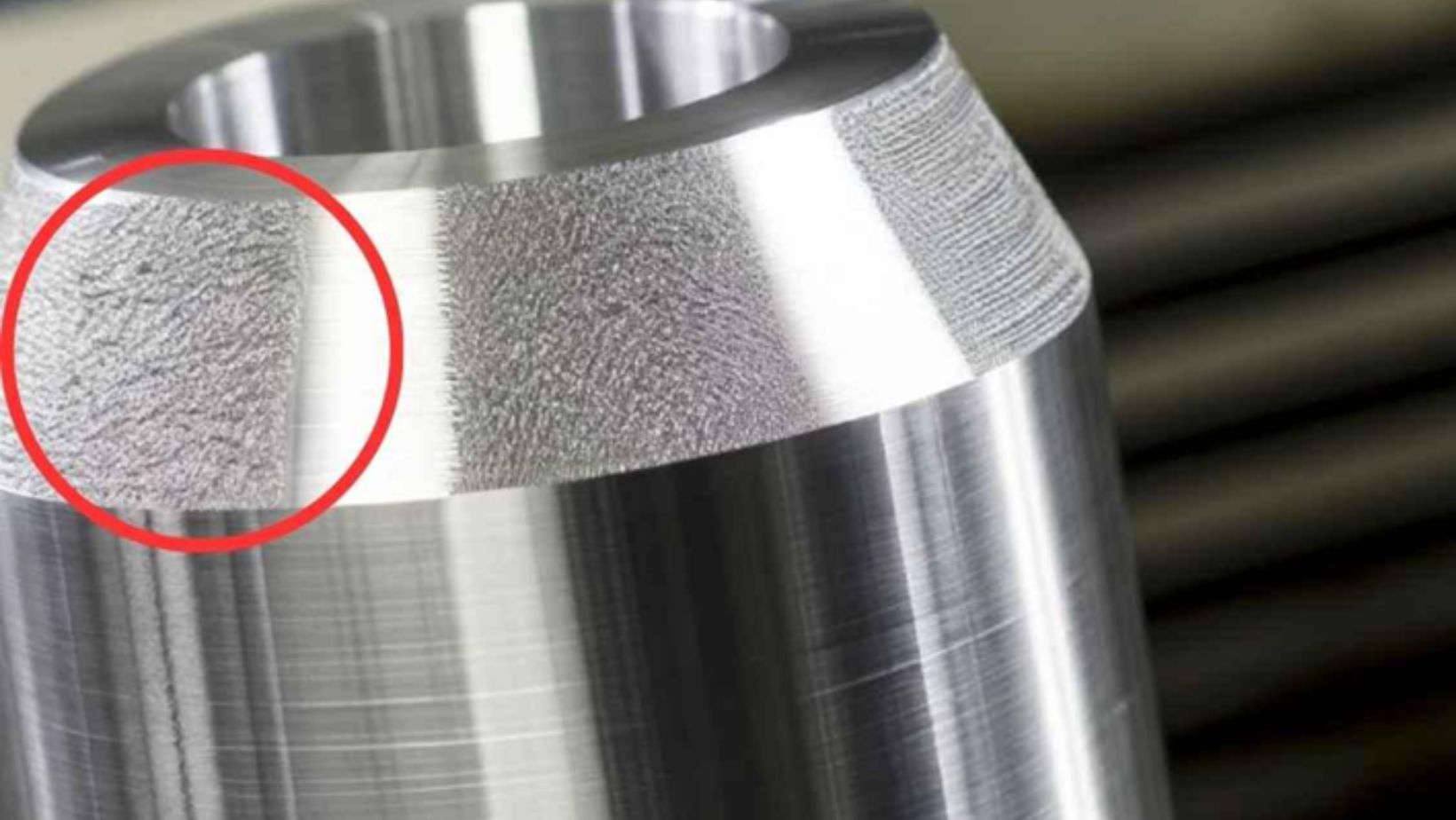
Flaws are presented as roughness, ribs, or uneven height, which can impact a part’s performance and aesthetical characteristics.
Cause:
Chatter and Vibration: The chatter in machining may arise from blunt tools, and wrong milling techniques also contribute to such surfaces.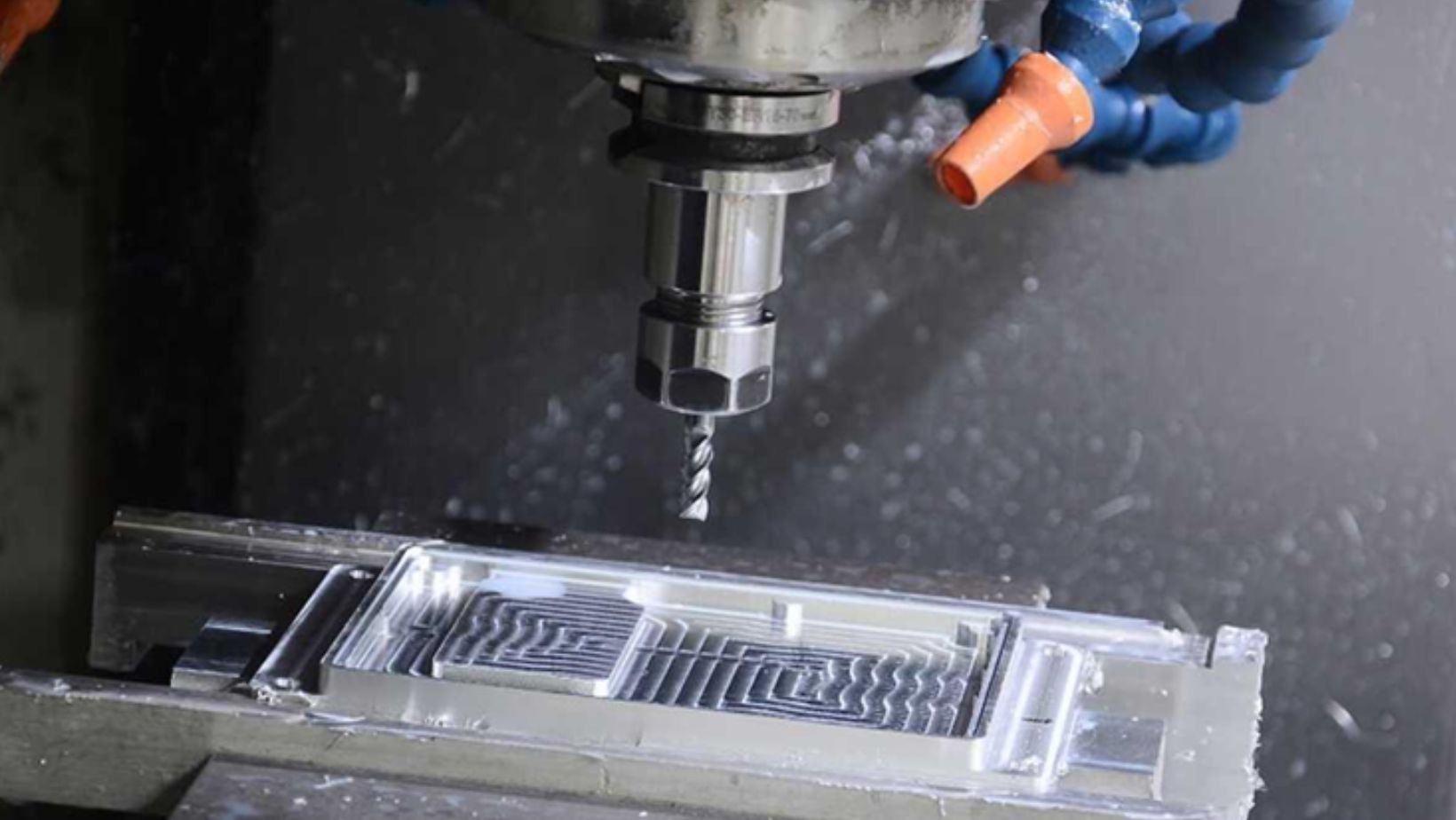
Incorrect Cutting Parameters: While utilizing high feed rates, the tools vibrate and thereby cause the surfaces to be uneven.
Solution:
Regular Tool Maintenance and Proper Strategy: These include the adequate use of sharp tools together with correct milling practices that help to minimize vibration.
Optimize Cutting Parameters: You can minimize machining defects by adjusting feed rates and spindle speeds for better workpiece finishing.
2. Burn Marks
Burr machining defects are damages caused by heat when working on a material through machining and lead to the formation of patches that are burnt.
Cause:
Improper Cutting Parameters: Inaccurate feed rates and speeds cause the tool to run hot.
Insufficient Cooling: Inadequate cooling results in overheating, primarily in heat-sensitive goods.
Solution:
Adjust Speed and Feed: To mitigate burr machining defects, reducing the feed rate compared to the speed is possible to reduce the amount of heat generated.
Optimize Cooling: Adjust cooling rates to manage heat, especially when working with titanium.
3. Dimensional Inaccuracies:
Dimensional inaccuracies are defects where the parts do not fit according to the required dimensions, and functionality.
Cause:
Machine Calibration Errors: A common concern with CNC machines is calibration problems causing inaccuracy.
Material Variations: Material properties cause variability that affects the precision being produced.
Environmental Factors: Its counterparts; temperature and humidity affect material and machine dimensions.
Solution:
Regular Calibration: Regular equipment calibration brings the right part.
Material Quality Control: To reduce size deviations, it’s recommended to use consistent materials.
Environmental Control: Fluctuations in temperature and relative moisture may reduce the reliability of measurement results.
4. Chatter Marks In Machining
Chatter Marks
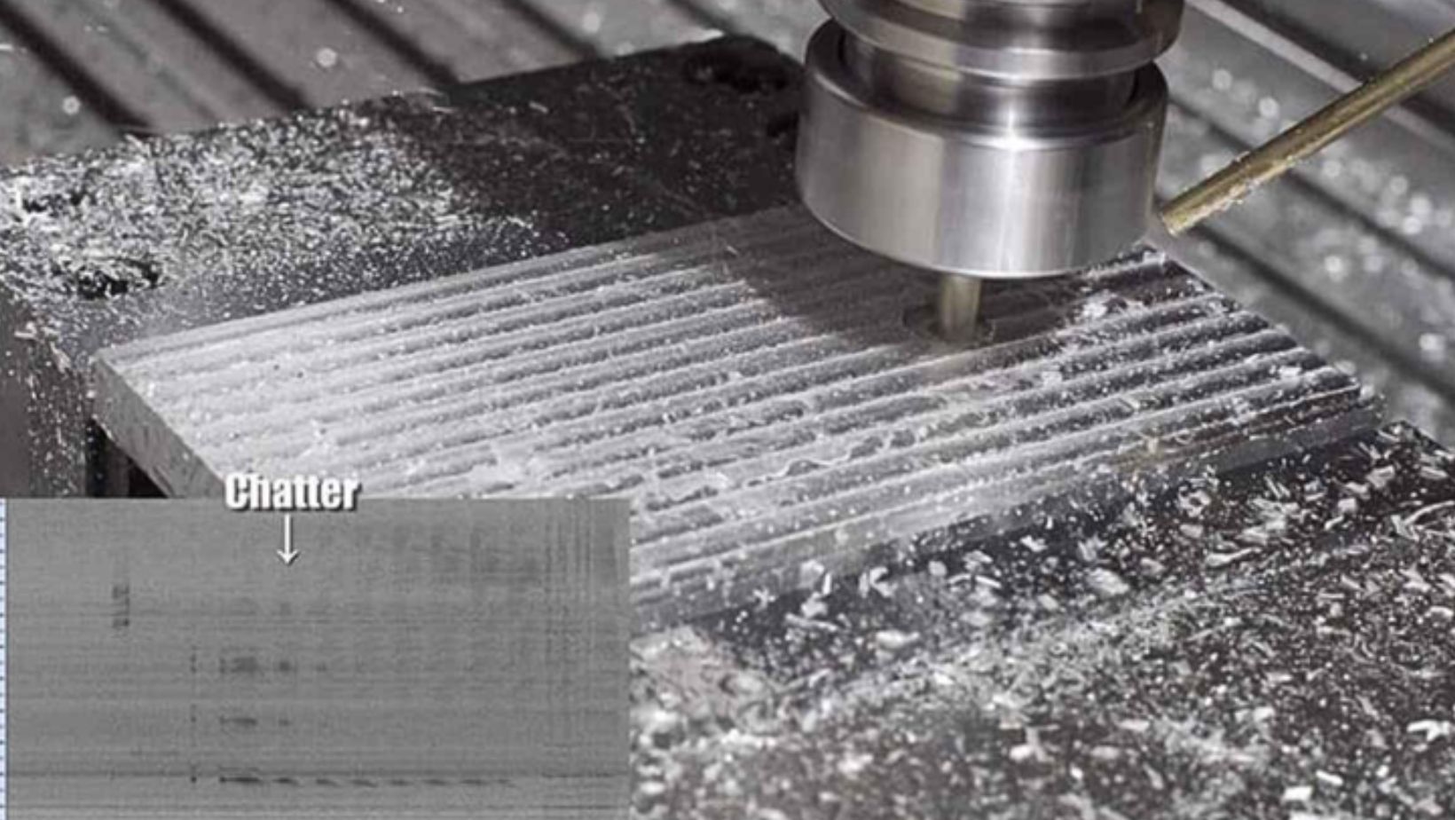
These machining defects are wavy lines on the surface and are a result of vibrations that occur during cutting operations.
Cause:
Unwanted Vibrations: These marks are a result of vibrations between the tool and the workpiece.
Tool and Workpiece Interaction: Unsatisfactory rigidity of the machine or the workpiece can increase vibrations.
Solution:
Optimize Cutting Conditions: Control the speed and feed rates to reduce vibrations.
Improve Workpiece Rigidity: If the workpiece is securely fixed; the chances of vibration are eliminated.
Vibration-Damping Tools: Specific accessories are used to reduce the intensity of vibrations to achieve better results.
5. Burrs
Machining Burrs
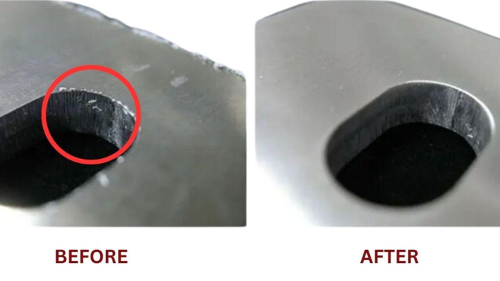
In machining defects, burr forms as projecting small spurs on the edges or corners of the machined part. Most burrs impact aesthetics and build the overall appearance of a piece of furniture, in addition to influencing its usability.
Cause:
Excessive Material Deformation: To prevent burr formation, avoid using softer materials or dull tools.
Improper Tool Path Settings: Burrs result from incorrect settings on tools.
Chipping of Material: Some materials can flake off and become a part of the tool edge.
Solution:
Deburring Processes: Try manual means such as files or sandpapers or even go for hi-tech thermal or vibratory methods of deburring.
Tool Optimization: Tools must be sharp and suitable for the job.
Process Adjustment: By chamfering the tool paths, and using chip deflectors, burrs can be eliminated.
6. Tool Marks
Tool marks manifest themselves as continuous or intermittent raised lines originating from the tool cutting edge.
Cause:
Incorrect Tool Selection: Marks can appear by using incorrect types of tools and high-pressure cutting.
Machine Vibration: The machine’s condition can affect the surface quality of the finished product.
Tool Entry and Exit: As it works the way it enters or exits the material causes some marks.
Solution:
Optimize Cutting Parameters: Optimize the pressure and the cutting conditions to prevent machining defects like tool marks.
Tool Selection: Select the right tools, which has the right coatings or geometries for the right applications.
Finishing Operations: Take grinding or polishing to erase the marks.
7. Deformation
Deformation is an unfavorable effect of CNC machining, which consists of changing the shape of the workpiece due to bending or twisting.
Cause:
Internal Stress Release: The used material can be stressed and tends to cause deformation.
Insufficient Support: Removing support too early during machining can cause shape changes.
Solution:
Appropriate Machining Methods: Appropriateness of methods to be used and optimum fixture support should be observed.
Post-Machining Stress Relief: To minimize the deformations apply thermal treatment.
8. Built-up Edge (BUE)
BUE occurs when chips are welded to the cutting tool’s edge.
Cause:
High Cutting Pressure and Heat: Makes the material stick on the tool.
Inappropriate Cutting Speeds and Feed Rates: These can raise the local contact stress and therefore increase BUE formation causing more friction.
Inadequate Coolant: If proper cooling is not applied hence heat accumulation increases.
Solution:
Tool with Damping Coating: Choose tools with coated or shaped to offer a low frictional surface with the workpiece.
Apply Lubricants and Coolants: Apply coolants appropriately during the machining.
9. Cracking or Fracturing
Cracking takes place when the machined part fails under load or splits.
Cause:
High Cutting Forces: Forcing the material beyond limits can lead to cracking.
Inappropriate Tool Path and Geometry: Improper tool setup is a problem that results in fractures.
Hardness of the Workpiece: When lighter materials are switched to the harder ones, then it’s easier for them to crack.
Solution:
Maintain Cutting Tools: Always blunt and polish the tools used in operating the equipment, to make a clean cut.
Use Hard-Coated Tools: Use tools, which comprise a carbide layer or diamond, for example.
Use Tools with Multiple Cutting Edges: Stress should be reduced on the cutting tool banks to minimize cracks by dividing the cutting forces appropriately.
10. Cuts or Poor Detail Resolution
Imperfect cuts or low detail acuity are characterized by missed outlines, where the CNC machine does not complete the work as intended.
Cause:
Inadequate Tool Sharpness or Selection: Stale or wrong tools are capable of provoking errors.
Incorrect Cutting Parameters: The wrong speed or feed rate may cause low detail resolutions that may affect the results.
Software or Programming Errors: Lack of proper programming can result in the development of incomplete cuts.
Solution:
Regular Tool Maintenance: Guarantee that cutting tools are taken for sharpening as often as possible.
Adjust Cutting Parameters: Increase or decrease the speed and feed rate to get better accuracy.
Ensure Machine Stability: Minimise vibrations for stability in the operation.
Refine CNC Programming: Make sure to verify programs for their credibility.
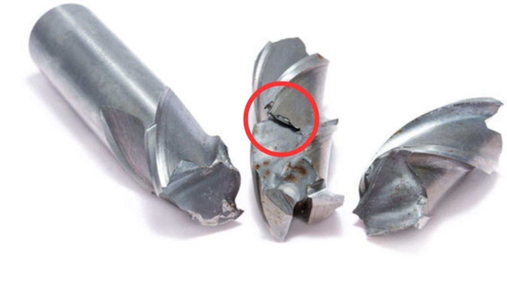
11. Tool Breakage
Broken Tools
Tool breakage is defined as the unexpected breakage of a cutting tool while in use during a machining process, leading to part destruction, and time-consuming repair.
Cause:
Excessive Cutting Force or Incorrect Feed Rate: High forces or wrong feed rates fail the cutting tool.
Inappropriate Tool Material: Tools may not be suitable for the workpiece material; so, the material must be compatible with the cutting tools used.
Inadequate Cooling or Lubrication: Failure to cool the engine leads to wear and tear of the parts involved.
Prolonged Tool Use: Tools are extended when a larger application is required for a specific operation besides the fact that they break, and wear out easily.
Solution:
Optimize Cutting Forces and Feed Rates: It’s important to ensure that parameters are set to avoid overstressing the organ.
Select Proper Tool Materials: Choose tool material concerning the workpiece.
Adequate Cooling: Make sure to use the right type of lubricants and coolants.
Regular Tool Inspections: Consumables should be replaced before failure.
12. Dents or Impressions
A dent/impression is an undesirable machining defect related to a surface feature that results from tooling or clamping processes.
Cause:
Excessive Clamping Force: High clamping pressure has detrimental effects on the impressions especially on soft materials.
Tool Impact/Improper Handling: Scratching or mishandling or any type of influence from the tool surface leaves dents.
Solution:
Use Intermediate Steel Plates: Place an equal amount of clamping force on the material for equal distribution of force for best results.
Invest in Special Chucks: Movable installations help to prevent material damage and avoid such CNC machining defects.
Adjust Clamping Force: Apply the least amount of force possible to clamp.
13. Mismatched Seams or Joints
Misaligned or irregular joints are seams or other junctions formed during the machining process where components are not fitted properly to each other.
Cause:
Inaccurate Programming or Tool Path Settings: Poor programming often leads to misalignment and other machining defects.
Machine Inaccuracy: Machine wear is one of the reasons that cause misalignment.
Inconsistent Material Properties: Misalignment is also brought about due to differences in material properties.
Clamping or Assembly Misalignment: Deviations in clamping contribute to joint misalignment.
Solution:
Accurate Programming: Programs and tool paths must be accurately designed.
Regular Machine Calibration: To ensure high levels of accuracy do not compromise, and maintain machines.
Use Consistent Materials: Hire a reliable and consistent source of machining materials.
Precise Clamping and Alignment: Follow proper steps when assembling the object, so that the assembled object will align correctly.
14. Pressure within and Strain
Internal stress and distortion involve situations whereby residual stress content in the material results in distortion during the process of material removal.
Cause:
Residual Stresses: Tensions from prior processes cause distortion and remain internal.
Uneven Cutting Forces: Inconsistent forces applied during the machining process lead to warping.
Inadequate Support or Clamping: When there is a lack of support, the material would be distorted in some way.
High Temperatures: High temperatures during machining can radially free the internal stresses.
Solution:
Stress-Relieving Treatments: Stress relieving should be done before the machining process.
Optimize Cutting Parameters: Balanced forces when cutting is another aspect observed to have variations.
Provide Adequate Support: Adopt good clamping and fixture support during the machining processes.
Control Machining Temperature: Employ the correct measures to avoid cases of overheating, and such machining defects.
15. Laminated Materials have Delamination
Surface Delamination
Delamination is a condition whereby layers of laminated stock separate during machining operations.
Cause:
Excessive Cutting Forces or Feed Rates: The layers may separate when high force or speed is applied to them.
Poor Quality Laminated Materials: Delamination is common with weak or improperly bonded materials.
Incorrect Tool Selection or Worn Tools: Inkjet and pin tools can cause delamination if the worn type is used.
Inadequate Clamping: Lack of enough clamping pressure results in movement and finally delamination.
Solution:
Lower Cutting Forces and Feed Rates: Ensure correct and suitable speed and force are applied to avoid layering in the material.
Use High-Quality Laminated Materials: Select good adhesive properties to prevent the formation of delamination.
Select the Right Tools: Laminated surfaces require sharp, appropriate tools suited for the specific materials in use.
Proper Clamping: Materials should be secured very tightly to minimize their movement when machining is being carried out.
16. Residual Material
Burr is an additional material that stays on the part after its cutting and is typically referred to as residual material.
Cause:
Deformation of Final Layer: The last layer of the material may even become deformed and leave a thin layer at the edges.
Solution:
Deburring: Clear burrs with heads of grinding, files, or sandpapers.
Advanced Deburring Methods: Vibratory and thermal deburring are the best methods of burr machining defect removal.
17. Corner Radius Issues
Corner Radii
Radii at corners gives rise to problems when corners have not been finished well.
Cause:
Forces During Machining: Pressures in concave corner areas can result in wrong radii measurements.
Solution:
Use Smaller Tools: It is recommended to use smaller tools to enhance the identification of concave corners to a certain extent.
Tool Size Adjustment: As a result, the tool size needs to be adjusted to decrease force and swing during corner machining.
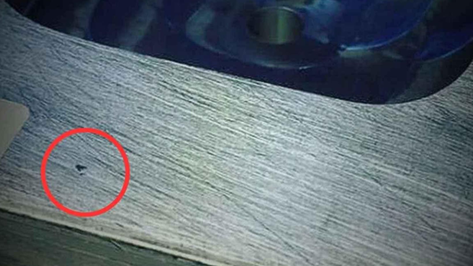
18. Swirl Marks
Swirl marks are circular patterns formed on the machined surface and affect both appearance and performance.
Cause:
Incorrect Feed Rates & Tool Speeds: When feed rates are high or low or when speeds are incorrect, the cutting patterns resulting are also uneven.
Solution:
Adjust Feed Rates and Cutting Speeds: Make sure to have the best settings to get that perfect finish.
19. Thermal Damage
Sources of Heat Generation
Thermal damage refers to the effects heat impacts on material, during the process of machining.
Cause:
High-Speed Operations or Insufficient Cooling: Any form of speeding or inadequate cooling results in the formation of heat.
Friction from Tooling: Tool friction can be fatal since it heats the surfaces which in turn damages the material.
Solution:
Optimize Cutting Speeds: Choose the right speed parameters for the material.
Maintain Tool Sharpness: Fine tools are required because they minimize wear and heat between the parts.
Improve Cooling Rate: Improve the ways of cooling especially for materials that tend to lose their properties when heated such as titanium.
20. Chip Recutting
Chip recutting occurs when chips are not properly cleared, causing the tool to cut them again.
Cause:
Inadequate Chip Evacuation: Inadequate evacuation results in chippings returning to the cutting area.
Improper Tool Paths: Recutting happens when tool paths are not well planned properly, thus incorrect tool paths are the leading cause of recutting.
Solution:
Improve Chip Evacuation: It’s a good practice to employ the correct techniques of chip evacuation.
Optimize Tool Paths: In this case, it is possible to modify tool paths to avoid recutting which is expensive and time-consuming.
Use Chip Breakers: Introduce chip breaker tools to control the chip size as well as its dispersion.
How Do CNC Machining Parameters Affect Machining Defects?
CNC machining involves factors such as speed, feed, and cut depth influencing the quality of the parts to be machined. Optimum control of such factors is crucial to minimize defects and increase the standard of work.
Cutting Speed:
Cutting speed refers to the speed at which the cutting tool is fed against the workpiece. A low cutting speed results in a buildup of heat and subsequently causes thermal damage both on the cutting tool and the workpiece. On the other hand, maximum cutting speed in an optimal range controls heat generation resulting in a good surface finish and fewer tools being used.
Feed Rate:
Another interesting factor is the feed capability; it regulates the rate at which the feed of the workpiece is performed by the cutting tool. When the feed rate is set high, friction and heat increase which affects the tool and surface finish qualities; the tool may break. On the other hand, a low feed rate will produce an undesirable material removal rate and longer machining time.
Depth of Cut:
The amount of material being cut by the tool in one complete operation is called a pass. Deep cuts can cause excessive load on the tool and machine which can lead to tool failure and rough surface finish. Due to the low penetration of the tool into the workpiece material, the machining rate and time may increase.
Conclusion
CNC machining defects have numerous parameters that determine its outcomes. The material properties, as well as the parameters which describe the machining process, are the most relevant ones because the optimal choice can significantly improve both, efficiency and accuracy, and minimize machining defects.
Other types of products, such as aluminum, stainless steel, plastics of various kinds, and composites, offer varying difficulties. Both types demand special measures to avoid such machining defects/imperfections as burr formation, thermal injury, and excessive tool wear.
.


